

If you've ever sourced sheet metal stamping parts for products ranging from automotive brackets to electronics chassis, you know that nothing kills a project timeline or budget faster than parts that don't fit together. As a sheet metal stamping supplier with nearly two decades of working with aerospace, consumer electronics, and industrial equipment clients, I've seen too many projects derail because of vague or overlooked geometric tolerance requirements. Tolerances aren't just fine print on a drawing-they're the difference between a part that assembles cleanly on the first try and one that requires hours of rework, scrap, and delayed delivery. In this post, I'll break down the core geometric tolerance requirements for sheet metal stamping parts, why they matter, and how we work with clients to nail these specs from the start.
First, let's ground this in what sheet metal stamping actually is: it's the process of cutting, bending, and forming flat sheets of metal (usually steel, aluminum, or stainless steel) into custom shapes using dies, presses, or laser cutters and press brakes. Geometric tolerances define the allowable variation in a part's shape, size, orientation, and position relative to other features-and they're non-negotiable for parts that need to interface with other components. For example, a sheet metal bracket that mounts a car battery needs to hold its holes within tight tolerance, because a misaligned hole could mean the bolt won't fit, or the bracket won't sit flush against the vehicle frame. For enclosures, a few thousandths of an inch of variation in bending angles could mean the lid won't close properly, exposing internal electronics to dust or damage.
The first set of tolerances I always focus on is size and linear dimensions. These are the basic measurements: length, width, thickness, hole diameter, and slot width. But here's the catch: sheet metal's inherent springback-when the metal bounces back slightly after being bent-means these tolerances aren't one-size-fits-all. For thin gauge sheet metal (16 gauge or thinner), we typically recommend size tolerances of ±0.005 inches for critical features, and ±0.010 inches for less critical areas like non-mounting edges. For thicker gauges (10 gauge or heavier), springback is more predictable, so tolerances can be adjusted to ±0.010 inches for critical features and ±0.015 inches for general dimensions. The key here is aligning tolerance to the part's function: a hole that's supposed to align with a mating bolt needs a tighter tolerance than a decorative edge that's only there for aesthetics.
Next, bend angle tolerance is one of the most common pain points in sheet metal stamping. Bend angles are usually specified as 90 degrees, but in reality, no bend is ever perfectly square. The allowable variation depends on two things: the bend's purpose and the material's thickness. For parts that need to snap together or press fit, bend angle tolerance should be ±0.5 degrees. For parts that fasten with bolts or screws, ±1 degree is usually sufficient. But if you're working on a high-precision application like a sheet metal chassis for medical equipment, we might push for ±0.25 degrees to eliminate any gap that could affect assembly. It's important to note that bend angle tolerance is not just about the angle itself-it's also about the bend location. A bend that's off by even 0.010 inches can throw off the entire part's overall dimensions, so we always link bend location tolerance back to the part's assembly requirements. For example, a bend that's 0.5 inches from a mounting hole can't vary more than ±0.008 inches, because that small shift would move the entire hole out of alignment.
Hole position and concentricity are another critical set of geometric tolerances for stamping parts, especially when multiple holes need to line up with mating components. Position tolerance (defined in GD&T, or Geometric Dimensioning and Tolerancing, terms) is the allowable zone where a hole's center can deviate from its theoretical perfect position. For automotive parts, where holes line up with frame components, we typically use a position tolerance of ±0.008 inches for critical mounting holes. For consumer electronics enclosures, which often have rows of holes for screws, position tolerance of ±0.005 inches is standard to ensure all screws line up without forcing. Concentricity, which applies to holes or shafts that need to share a central axis, is important for parts like bushings or rotating components. For example, a bushing that mounts a fan blade needs concentricity tolerance of ±0.003 inches to prevent vibration and wobble, which would shorten the fan's lifespan. If you're working on a project that requires precise hole alignment, it's worth noting that our team uses CNC stamping and laser cutting tools (check out our Sheet Metal Laser Cutting Bending Welding Service) to hold tight tolerances consistently, even for high-volume runs.
Flatness and perpendicularity are two more geometric tolerances that are often overlooked but can make or break a part's performance. Flatness is the allowable variation in a part's surface, measured as the gap between the part's surface and a reference plane. For a sheet metal chassis that needs to sit flat on a table or interface with another flat component, flatness tolerance of ±0.010 inches is standard. For heat sinks or enclosures that need to mount electronics that are sensitive to warping, we might tighten flatness to ±0.005 inches to ensure no component is tilted or sitting at an angle. Perpendicularity, which is the angle between two surfaces or features that should be 90 degrees, is critical for parts with bends that need to be square to each other. For example, a junction box that needs to mount on a wall has a back plate that should be perpendicular to the side plates. Perpendicularity tolerance of ±0.015 inches ensures the box sits flush against the wall without gaps. If you're sourcing junction boxes, our Sheet Metal Junction Box Fabrication service is optimized to hold these flatness and perpendicularity specs, even for custom-sized boxes.
Roundness and straightness round out the core geometric tolerances for sheet metal stamping parts. Roundness applies to circular features like holes, pipes, or bushings, defining how much the feature can deviate from a perfect circle. For a mounting hole that needs to fit a bolt tightly, roundness tolerance of ±0.003 inches ensures the bolt seats evenly without wobbling. Straightness, on the other hand, applies to linear features like slots, edges, or bent sections. For a long slot that runs along a bracket, straightness tolerance of ±0.010 inches over the slot's length ensures the slot's walls are straight, so a fastener can slide through without getting stuck.
Now, it's not just about defining these tolerances-it's about applying them correctly, because over-tolerancing (making specs tighter than needed) can drive up material and labor costs, while under-tolerancing leads to parts that don't work. For example, if you specify a position tolerance of ±0.002 inches for a hole that only needs to align with a loose-fitting screw, you're adding unnecessary cost because the stamping process has to run slower and use more precise tools. Our approach as a supplier is to work closely with clients at the design stage to balance tolerance requirements with cost. We'll ask questions like: does this feature need to mate with another part? What's the functional consequence of a small variation? For non-critical parts like decorative trim, we can relax tolerances to save money, while keeping tight specs on critical assembly features.
It's also important to account for secondary operations when setting tolerances. Many stamping parts go through post-processing like powder coating (check out our Polyurethane Powder Coating Service) or bending. Powder coating adds a thin layer of material (usually 0.002 to 0.005 inches thick), so we need to adjust hole diameters and bend dimensions to compensate for this. For example, a mounting hole that fits a bare bolt might need to be 0.005 inches larger if it will be powder coated, to ensure the bolt still fits after the coating is applied. If you're working on enclosures, our Sheet Metal Enclosure Fabrication team accounts for coating thickness in every part, so you don't end up with parts that don't fit after finishing.
Another factor that affects geometric tolerance is material type. Different metals have different springback rates, which means they'll deflect differently after stamping and bending. Aluminum, for example, has more springback than mild steel, so we typically add a small amount of extra bend angle when stamping aluminum parts to compensate. Stainless steel, on the other hand, is more rigid, so bend angles hold their shape more consistently. Knowing your material's properties is key to setting realistic tolerances-we never recommend a bend angle tolerance of ±0.5 degrees for thick stainless steel, because it can't hold that precision, leading to wasted parts and delays.

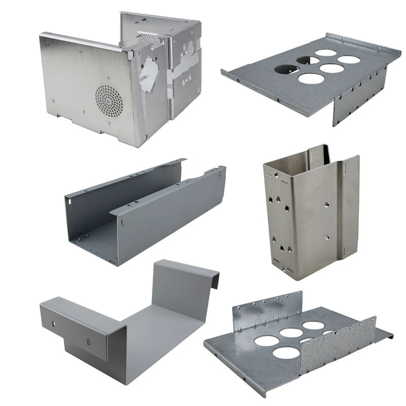
Quality control is the final piece of the puzzle when it comes to meeting geometric tolerance requirements. Even if specs are clear, a stamping process can have variation, so we use coordinate measuring machines (CMMs) and visual inspection tools to check critical features for every production run. For high-precision parts, we do 100% inspection of critical dimensions, while for low-volume, non-critical parts, we sample every 50 units to ensure consistency. We also provide detailed inspection reports with every order, so you can verify that parts meet your tolerance requirements before they ship. For chassis parts, our Sheet Metal Chassis Fabrication service includes full inspection reports for all critical features, so you can trust that the parts will assemble correctly.
At the end of the day, geometric tolerance requirements for sheet metal stamping parts are all about alignment-between your part's function, the material properties, the stamping process, and the post-processing steps. Too often, clients treat tolerances as an afterthought, leading to costly reworks and missed deadlines. As a supplier, we partner with clients from the design stage to final delivery, helping them define realistic, functional tolerances that balance performance and cost. If you're working on a project that requires sheet metal stamping parts, whether it's a chassis, junction box, enclosure, or custom component, our team is here to discuss your tolerance needs, walk you through our capabilities, and provide high-quality parts that meet your specs on time. Reach out to our procurement team to start a conversation about your project-we're ready to help you avoid the common pitfalls of poor tolerance planning.
References:
- ASME Y14.5-2018, Dimensioning and Tolerancing. The American Society of Mechanical Engineers, 2018.
- Kalpakjian, S., & Schmid, S. R. (2020). Manufacturing Processes for Engineering Materials (7th ed.). Pearson Education.
- Sheet Metal Stamping: Design for Manufacturability Guidelines. Society of Manufacturing Engineers, 2021.
- Metal Forming Tolerance and Quality Standards. International Organization for Standardization, ISO 2768-1:2019.